Nurbs: An Introduction
NURBS modeling has been around since the advent of 3D modeler software. Gradually, it has paved its way to becoming the ideal choice for carrying out computer-aided modeling. There are main reasons for its popularity. For example, it helps in the accurate representation of standard geometric objects.
The amount of information required to represent the NURBS geometry is lesser than faceted approximations, and so on.
This article will help you to get a deeper insight into its advantages. However, before we move to that topic, let us understand the concept first.
What are Nurbs?
NURBS, stands for Non-Uniform Rational B-Splines, are a type of Bezier curves. This Nurbs curve is defined by four things: degree, control points, knots, and an evaluation rule. It is generated through a mathematical formula. In simple terms, Nurb is a mathematical representation of complex 3D geometry. NURBS cannot be referred to as surfaces, but you can create NURBS surfaces by interjecting a surface amid NURB splines.
What is NURBS Modeling?
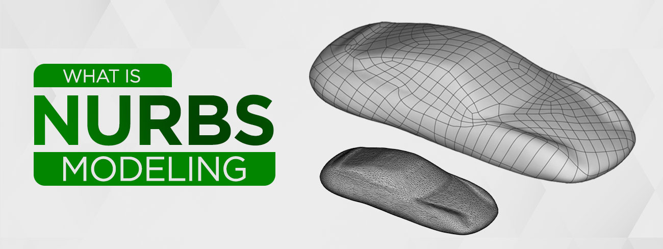
NURBS Modeling is the process of using the geometrical shapes ranging from 2D lines, circles, arcs, to create detailed and flexible free form solid 3D models by using complex mathematical equations.
NURBS models are highly accurate and flexible. This renders them fit for surface modeling of all processes like complex animations, detailed illustrations, and designs meant for sending to the production assembly line. In Maya 3D, you can use NURBS, subdivision surfaces and polygons for creating 3D curves, surfaces, and various geometry types.
Another technique is quite similar to that of NURBS modeling. It is polygonal modeling. However, one way to differentiate NURBS vs. polygon modeling is how the computer calculates the meshes. In the former technique, the meshes are calculated as splines, whereas in the latter, it is calculated as polygons.
Curves for Graphic Representation
In 3D computer graphics, curves are widely used for achieving various effects. Different types of curves in CAD can be used for the creation of vector graphics, 3D models, animated sequences, and for defining different TrueType fonts. Curves are in different forms.
Curves can be used easily in some cases. Certain curves can be nimbly used for defining different types of shapes. Some curves can be implemented with ease and proper acceleration can be achieved with graphics hardware. The types of curves in computer graphics are mainly categorized into three, i.e., implicit, explicit, parametric. However, they are commonly encountered in the form of Bezier and NURBS.
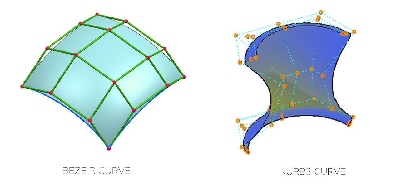
What is a Bezier curve?
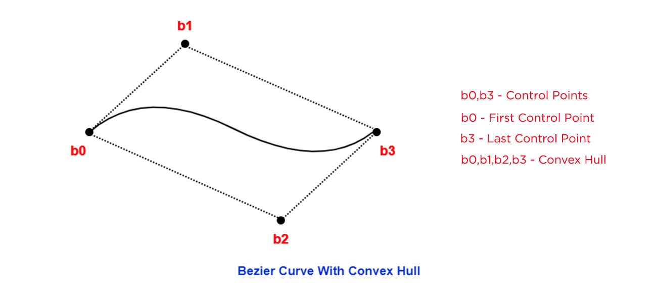
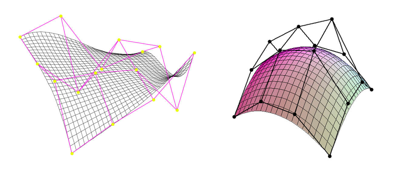
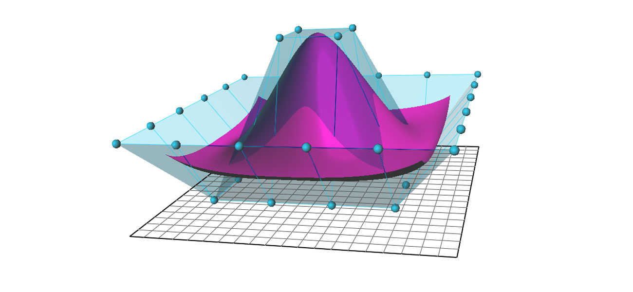
The generalized version of the Bezier curve is NURBS. In any Bezier curve, there would be controls points or control handles and control polygons. This curve is usually present inside the Convex Hull of control points. However, you can make predictable changes in the shape of the curves by manipulating the position of control points.
The point on the Bezier curve, like different types of curves, is actually the weighted sum of different control points present. This implies that each control point influences the behavior of other point. At the starting of the curve, optimum impact is exerted by the first control point. In the curve’s first half, the second point would have maximum impact. This process goes on as the curve progresses.
The formation of final curve is influenced by every control point. The influencing pattern is dictated by blending function assignment. Through the blending function, the weight of control point at each section of the curve is defined. 0 value is indicative of the fact that any point of the curve is not getting affected by that control point. When the value of bending function is 1, it indicates that the curve would intersect the control point.
The curve’s properties are defined by the attributes of the blending functions. Polynomial functions of certain degrees are used by Bezier curves. The curves that are formed demonstrate the following properties:
- The starting point of the curve is first control point
- The termination point of the curve would be the last control point
- Usually, the curve won’t intersect the control points lying in between
- The inner control points would control the curve’s tangent
- The tangent would be controlled at the termination points
- The curve would always lie within the control polygon’s convex hull
Degree of the Curve
The curve type that is commonly used is degree 3 cubic curve. The maximum value of exponent within the polynomial blending function, in case of Bezier curves, is represented by the degree. The Bezier curve can be of any degree.
The degree 1 curve consists of two control points and is in the form of a normal line. Arc is the shape of a degree 2 curve which is constituted of 3 control points. As the number of control points go on increasing, the degree of the curve also goes up and the shape becomes more complex. However, curves of higher degree are difficult to handle as every control point continues to influence the entire curve.
The Rational Curve
Weight is assigned to every control point within a rational curve. The degree by which the curve is attracted to the point is defined by its weight. The absolute value of the control points is not as important as their relative weights. You will find that the shape of the curve whose all weights are set to 1 is alike to that of the curve in which all weights are 100 in value. Changes in the shape occur when the control points’ weights vary.
Rational Bezier curve’s special instance is the normal Bezier curve in which all the weights have equal value. Graphics designers can use the various options offered by rational curves but they have to grapple with highly complex algorithms and more data sets.
B-Splines
In a B-Spline, a number of Bezier arcs are present. The continuity at the joints are defined by a unified technique provided within B-Spline. The multiple parts of the curve are kept together by B-Splines with the help of external factors. However, the integrity of control points is retained.
Certain control points are shared by the neighboring curves. A knot vector determines the external factors which render the curves uniform or implicit and non-uniform or explicit. The amount of information to be shared by neighboring curves or segments is defined by the Knot vector.
Advantages of NURBS
NURBS offer a number of benefits. These include:
- Different types of organic 3D curves and shapes can be constructed
- Curves are of smoothened type and of minimal nature
- NURBS surface can be constructed with ease
- Surfaces can be constructed with ease
- Surface types find wide application in different domains
- Games, visualizations, industry modeling, animations etc. are done with NURBS
- 3D NURBS data type can be exported to CAD software applications with ease
- IGES file format is used for surface export to CAD programs
- In Maya, Bezier curves can be imported as well as the NURBS data type
- NURBS data can be imported from different CAD applications in Maya
- NURBS curve can be open, closed, or clamped
Additionally, if you want to put polygon surface types in use for your project, you can start with construction of the surfaces through NURBS first and then get them converted to polygons.
Use of NURBS Primitives
3D models can be constructed from NURBS primitives. The primitives are basically 3D objects which are in the form of usual geometric shapes like conical, spherical, cubical and likewise. Many 3D shapes can be created with the initial help of primitives.
Shapes can be modified by changing the attributes of the NURBS primitives. Modification of the NURBS primitives can also be accomplished by cutting off unwanted parts of the basic forms, getting the edges’ beveled, and using the sculpting tools to sculpt the shapes in desired forms
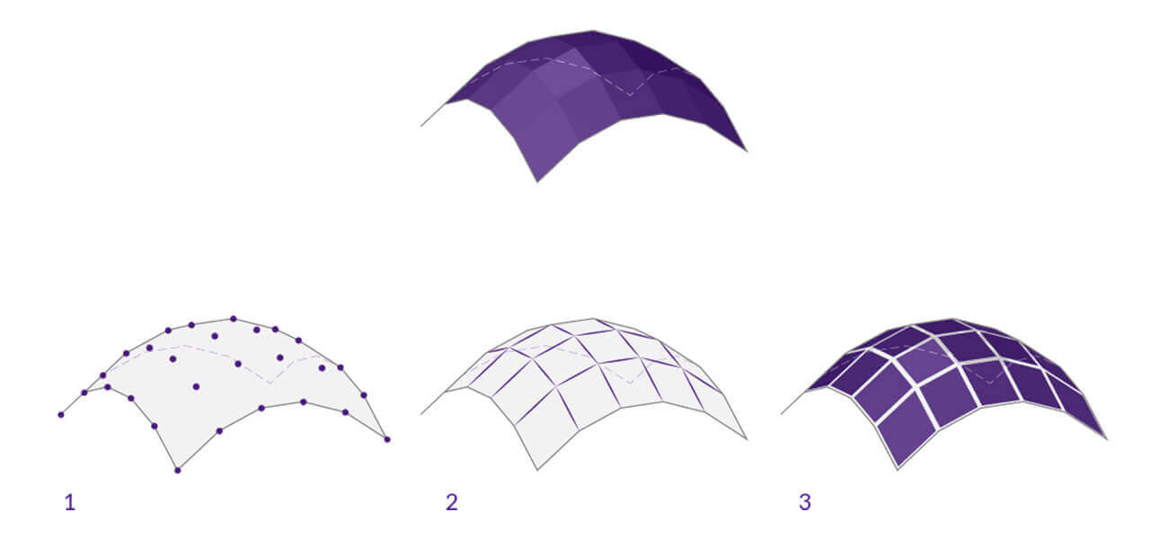
Use of NURBS Surfaces
3D models can also be constructed out of NURBS surface. The 3D form’s basic outline is defined by the construction of NURBS curves. Once the curves have been developed, you can use them for construction of NURBS surfaces.
The construction and modification of NURBS curves as well as surfaces can be done in following manner:
- Control vertices or edit points can be placed for drawing curves
- Within the Create Menu, the tools for drawing curves are located
- Another important menu set is the modeling menu
- Over here, you can find options for creation and editing of NURBS curves/ surfaces
- In the Curves/ Surfaces shelf, NURBS options are also present
Why Nurbs Geometry is Ideal for CAM?
NURBS geometry possesses certain essential qualities which renders it perfect for computer aided modeling. These are:
- NURBS geometry can be exchanged with the use of many industry approved methods
- Once the model is handed over to customer, the customer can port the models easily
- This retains the valuable aspect of geometric models
- Models can be ported to different engineering analytic, rendering, modeling or animation software
- It can keep geometric information in a manner which is useful for future
- Future advances in 3D shapes can take advantage of NURBS
- The technique is defined in an accurate manner as per the standards
- Most universities deal in mathematical and computing theories behind NURBS
- Trained professional nurbs modeler who can handle and leverage NURBS geometry are easily available
- Programming for NURBS can be done for engineering, software, industrial design and other verticals
- Tailormade software programs can be developed based on NURBS
- Both standard and freeform geometrical shapes can be precisely represented by NURBS
- Standard objects are in linear, circular, ellipsoid, spherical, or in tori forms
- Human or vehicle bodies constitute free-form geometrical shapes
- The quantum of information needed to represent NURBS geometry is significantly lesser
- In contrast, common faceted approximations use much more information
- Accurate implementation of the evaluation rule for NURBS is done easily on any computer efficiently
NURBS vs Polygonal Modeling
The below points will help you to understand the differences between the two modeling techniques
- In polygon modeling, meshes are calculated as polygons while in NURBS modeling, they are calculated as splines. Polygons are usually flat shapes comprising a 3D shape. On the other hand, splines can create curves from a single geometry section.
- NURBS surfaces are the mathematical representations used in 3D modeling process to create the smooth and curved surfaces. NURBS calculates the model’s surface by using complex geometry. It means the technology works better for models that need more precision. But, it has a downside. It is not appropriate for applications that need faster rendering.
In the case of polygon modeling, it calculates the straight lines between the points. Also, it cannot make a perfect and smooth curve. However, you can create the perception of a smoother curve. This can be done by increasing the number of polygons and employing smoothing groups.
- Another feature of NURBS that makes it different from polygon modeling is that the size of the NURBS file is smaller. Besides, the data are stored as mathematical points and are easier to read and understand.
However, in polygonal modeling, the data might be a little complicated. It may also end up as corrupted meshes while transferring the polygon models.
Conclusion
NURBS curves are highly useful in creation of simple as well as complex 3D shapes. The technique of NURBS modeling in Maya is simple and a bit of focused practice can make anyone proficient in using it.
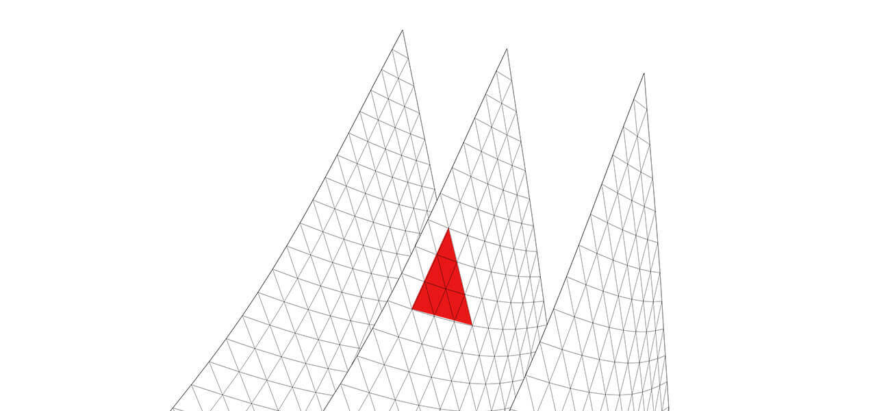
The presence of significant number of control points on the NURBS surfaces make them difficult to use. Many 3D modeling software offers simplification methods to help you optimize on the full potential of NURBS surfaces.
Have any 3D modeling related requirement?
Contact Us